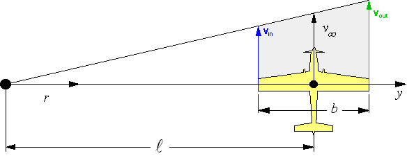
Top view of a control line model,
flying at velocity ![]() .
.
Aerodynamics of Control Line Models |
When a model flies tethered, its inboard and outboard wing tips sweep over circular paths having different lengths. This motion results in a linear variation of the air velocity from the center post towards the outer wing tip of the model. Aerodynamic forces are directly related to the square of the velocity of the onset flow. Thus one can expect that the outboard wing will create more lift and drag than its inboard companion. One can imagine, that the total lift force is not acting on the fuselage center line anymore, but is shifted towards the outboard wing. The question is: how large is this effect?
|
Top view of a control line model,
flying at velocity |
The local velocity at a spanwise position y (measured outwards from the fuselage center line) is given by
 |
After inserting the y-position of the wing tips (±b/2) into this formula one can write
 |
for the ratio of the velocities at the outboard respectively the inboard wing tip.
If the line length is large compared to the wing span b, this ratio becomes unity. The shorter the lines compared to the wing span, the larger is the variation of the flow velocity over the wing.
|
Rear view of a control line model with Lift L, rolling Moment M and eccentricity a. |
First we cut the wing into small segments and derive an expression for the lift force acting on a segment
The area of a wing segment having a chord length c(y) and width dy is
|
|
The lift force of such a wing segment is
and its contribution to the rolling moment
The lift force can be calculated by integrating the lift distribution along the span:
 |
The expression for the rolling moment around the fuselage x-axis is:
 |
We can evaluate the integrals if we assume a rectangular wing (chord length c) without twist having the same lift coefficient Cl over its span. The results will give an indication of the effect and whether it is worth to examine it in detail for other wing planforms.
Solving the expressions for lift L yields:
 |
and for the rolling moment M one finds (positive: rolling towards the center post)
 |
The eccentricity of the lift force can be found from
 |
Here a is measured from the fuselage center line, positive values indicate that the lift acts on the outboard wing. For a typical control line model, the value of a is small, in the order of 2-5% of the wing span so that it can be safely neglected, especially considering the basic assumptions of constant Cl along the span.
Last modification of this page: 21.05.18
![]()
[Back to Home Page] Suggestions? Corrections? Remarks? e-mail: Martin Hepperle.
Due to the increasing amount of SPAM mail, I have to change this e-Mail address regularly. You will always find the latest version in the footer of all my pages.
It might take some time until you receive an answer
and in some cases you may even receive no answer at all. I apologize for this, but
my spare time is limited. If you have not lost patience, you might want to send
me a copy of your e-mail after a month or so.
This is a privately owned, non-profit page of purely educational purpose.
Any statements may be incorrect and unsuitable for practical usage. I cannot take
any responsibility for actions you perform based on data, assumptions, calculations
etc. taken from this web page.
© 1996-2018 Martin Hepperle
You may use the data given in this document for your personal use. If you use this
document for a publication, you have to cite the source. A publication of a recompilation
of the given material is not allowed, if the resulting product is sold for more
than the production costs.
This document may accidentally refer to trade names and trademarks, which are owned by national or international companies, but which are unknown by me. Their rights are fully recognized and these companies are kindly asked to inform me if they do not wish their names to be used at all or to be used in a different way.
This document is part of a frame set and can be found by navigating from the entry point at the Web site http://www.MH-AeroTools.de/.