Users Manual |
JavaProp presents itself in a single window or in a single applet area in your browser. It contains a row of tabs on top and a card area below. Each tab shows its associated card which contains input and output elements for a certain topic.
The cards are divided in topics like Design, Airfoils, Geometry, Analysis and Options. Most of these cards have a button bar at the bottom, which contains command buttons acting on this specific card. Depending on the security settings of your Java system, some of these buttons may be inactive (see Applet or Application). Each card is described in more detail in the following sections. Note that when you install JavaProp locally, a more extensive users manual in PDF format will also be installed..
In JavaProp you work with a single "virtual" propeller. This means, that you have a single propeller, which can be designed, analyzed, modified and analyzed again an so forth. All manipulations like airfoil choice, specification of diameter or r.p.m. setting, applying modifications to the blade shape and importing a new blade geometry will alter this virtual propeller.
The unit system is metric for all entries and results, if not noted otherwise. Some conversion relations for metric and imperial units are given on the Tips and Tricks page.
Printed user's manual:
This page presents a short overview only. You can
download a PDF version of a more
detailed user's manual.
Design Card |
|
| The design card contains all data entries for the design of an optimum propeller. This propeller will have the highest efficiency for the given design point. Some entries like diameter and velocity of rotation are also used for the analysis of propellers. Additional parameters for the design are the design lift and drag coefficients of the airfoil, which must be selected on the Airfoils card. Also, the density on the Option cards must be set correctly for your problem. | |
| The velocity of rotation n is given in revolutions
per minute, but for the actual calculations, as in the advance ratio v/(nD),
n usually means revolutions per seconds. You can design a propeller either for given power, thrust or torque. To start a design, simply push the "Design It!" button. After an optimum propeller has been designed, the results for the design point are listed in a text area below the input fields. If a spinner diameter is given, it is handled as a simple through flow hole in the center of the propeller. |
 |
| The shrouded rotor option only switches the tip
loss correctionoff , the shape of a shroud is not take into account, nor is its
thrust and drag. A square tip option can be used to maintain a finite chord length at the tip. This is achieved by simply extrapolating the chord lengths of the last two sections towards the tip. A wind turbine can be designed by entering an arbitrary negative value for the power. Note: the design procedure also uses the distributions of airfoil sections and the design angles of attack from the Airfoils card.. |
|
Airfoils Card |
|
| Here you can select which airfoils you want to use along the
radius. You can also select a design angle of attack, which is only used for
the distribution of lift and drag coefficients for the design of an optimum
propeller on the Design card. The right hand side of the card shows the airfoil polar of the station you are currently working on and also indicates the lift and drag coefficient for the specified angle of attack by symbols. When you select a different airfoil or change the angle of attack, the screen is updated accordingly. |
 |
| The current version uses synthetic airfoil data, which are
characterized by 30 parameters, mainly by zero lift direction, maximum lift
coefficient and minimum drag coefficient (look here
to see some of the the synthetic polars used in the propeller code). The
Reynolds number is fixed so that you might want to check the local Reynolds
numbers to select the appropriate polar. The selected airfoils are used for the design as well as the analysis. Currently, you can select from the following canned airfoils only: |
|
|
|
|
|
|
|
|
|
|
|
|
|
|
|
|
|
|
|
|
|
|
|
|
Geometry Card |
|||||||||||||||||||||||||||||||||||||||||
| This card shows the geometry of the current propeller. Besides the distributions of the chord length c and the blade angle ß in normalized as well as in true dimensions it also shows the local pitch height distribution H. | |||||||||||||||||||||||||||||||||||||||||
| The button bar has an "Import..." button, which can
be used to import any arbitrary geometry. The Import window contains a text
area, where you can enter rows of radius, chord and blade angle to describe
your blade. Each row should describe a single radial station and entries
must be separated by blanks or tabs. JavaProp performs a linear
interpolation by assuming straight lines between the data you have supplied.
If you specify a single station only these data will be assumed to be valid
for the whole blade, two rows of data describe a straight tapered blade,
with a linear twist distribution. In most cases it is a better idea to start
with an optimum design propeller and to use the Modify card to change the
chord and pitch distribution to your likening. Note: When the Import window is brought up and the clipboard contains some text, this text is preloaded into the text area. So you can copy a table prepared e.g. in Excel to the clipboard, bring up the Import window and import the geometry into JavaProp. |
Note about my x-y graphs: You can copy most of the graphs to
the clipboard in AutoCad DXF, Adobe Illustrator encapsulated Postscript or
SVG vector graphics format by pressing the right mouse button while the
mouse pointer is located over the graph (context menu). |
||||||||||||||||||||||||||||||||||||||||
You can export the geometry to a file in
several formats:
Depending on the file name extension, one of these formats is selected (extensions are case sensitive!). |
|||||||||||||||||||||||||||||||||||||||||
|
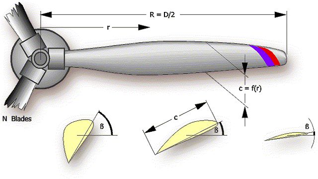
The sketch shows the parameters which describe the geometry
of a propeller. The local chord length c and the blade angle ß
(twist angle) are depending on the radius coordinate r. |
|||||||||||||||||||||||||||||||||||||||||
Modify Card |
|||||||||||||||||||||||||||||||||||||||||
| This card makes it possible to modify a propeller in several ways. These geometric modifications are applied to the current geometry. Therefore a sequence of modifications adds each modification to the result of the previous change. | |||||||||||||||||||||||||||||||||||||||||
| Often you want to modify a blade so that it better fits your
needs or manufacturing methods. For example it is sometimes desirable
to have a straight tapered blade instead of the curved planform coming out
of the optimum design method.
To achieve this, you can modify the blade in various ways. The card offers several modifications, which are all applied in sequence, from top to bottom. Usually it makes sense to perform only one modification and to reset the parameter afterwards to avoid any further, undesired changes. An additional feature on this card is to specify a simplified axial inflow profile, e.g. resulting from a wide fuselage or a large spinner. |
 |
||||||||||||||||||||||||||||||||||||||||
|
|||||||||||||||||||||||||||||||||||||||||
Multi-Analysis Card |
|||||||||||||||||||||||||||||||||||||||||
| This card can be used to start an automatic
analysis run, which starts at static conditions and proceeds to higher
advance ratios until the efficiency drops down to negative values and the
propeller starts to act as a windmill. The analysis is performed at fixed intervals of v/(nD) but the step size is adapted and reduced when the efficiency begins to drop. |
|||||||||||||||||||||||||||||||||||||||||
| Results are listed in form of the usual propeller
performance coefficients as well as actual velocity, thrust and power
values. The output also contains values of
η* (eta*) which is the maximum possible efficiency for the
current power loading. One column is labeled stalled - it lists the
percentage of the blade where the local airfoils are operating at angles of
attack beyond stall. Additionally an exclamation mark (!) appears in this
column when the power loading is too high for the theory to give accurate
results. This usually happens at low advance ratios. Graphs of some results are placed on separate cards in the lower part of the card. These can be selected by clicking on the appropriate tab. Note that all results in coefficient form are generally applicable. On the other hand all dimensional data like thrust and power are calculated for the settings found on the Design card. Additionally the fluid density is taken from the Options card. If you mount a propeller on a given engine its speed of rotation will depend on the characteristics of the engine. Therefore you have to check and possibly adjust the speed of rotation to match points on the performance curve of your specific engine. |
 Note: You can copy the graphs to the clipboard in various graphics formats using the right mouse button context menu. |
||||||||||||||||||||||||||||||||||||||||
Single-Analysis Card |
|||||||||||||||||||||||||||||||||||||||||
| This card can be used to start an analysis for a single advance ratio, which is determined by the values of axial velocity v, speed of rotation n and diameter D from the Design card. | |||||||||||||||||||||||||||||||||||||||||
| The table lists the distribution of the aerodynamic
coefficients for lift and drag, ratio of lift to drag L/D as well as
the local Reynolds and Mach number. Information about the slip stream behind
the propeller is included in form of the induced flow factors a and a',
which describe the magnitude of the additional velocity in the slip stream
at the propeller . The angles δ (delta)
and δff (delta_ff)
describe the swirl angle of the flow immediately at the propeller and far
behind it (far field). finally some coefficients to calculate
structural loads are included. More details can be found on the page Propeller Analysis. |
 |
||||||||||||||||||||||||||||||||||||||||
Flow-Field Card |
|||||||||||||||||||||||||||||||||||||||||
| This card presents an approximated view of the slipstream of
the propeller. Like the "Single Analysis Card" it runs an analysis for a
single advance ratio. It shows a cross section of the flow, extending from
in front of the propeller (x = -2R) to behind the propeller (x = +2R).
The border of the slipstream is indicated by a black outline. The color spectrum in the upper part of the card shows the axial velocity from undisturbed inflow (blue) to fully accelerated flow (yellow). The acceleration takes place in front as well as behind the propeller plane and the ratio of the axial velocity to the inflow velocity Vx/V is printed for two locations. In front of the propeller the ratio should be close to 1.0, whereas behind the propeller, the acceleration can be seen. A value of 1.3 means that the axial flow Vx is 30% faster than the flight speed (inflow velocity V). |
 |
||||||||||||||||||||||||||||||||||||||||
Options Card |
|||||||||||||||||||||||||||||||||||||||||
| This card offers some information about your Java system and
it contains a combo box to select a different country setting. The country
setting affects the decimal separator only, the language will be
automagically selected based on your system settings (or according to your
command line parameters).
The default language is English, but if you want to provide a new language, contact me by email to receive a file with the required text to translate. Also, you can specify some properties of the fluid where you want the propeller to operate. The most important parameter is the density of the fluid, which controls the chord width of the propeller blades. The kinematic viscosity is needed for the calculation of the local Reynolds number as the speed of sound is used to derive the Mach number.
|
 |
||||||||||||||||||||||||||||||||||||||||
| JavaProp can also be used to design and analyze
propellers for marine applications ("Hydroprops")
provided that these operate fully submerged and without cavitation. Note that the density of water is higher by a factor of about 1000 than the density of air. This directly affects power and thrust.
25°C = 59 F 35°C = 95 F |
Typical values for air are given in the following
table:
|
||||||||||||||||||||||||||||||||||||||||
Last modification of this page: 21.05.18
![]()
[Back to Home Page] Suggestions? Corrections? Remarks? e-mail: Martin Hepperle.
Due to the increasing amount of SPAM mail, I have to change this e-Mail address regularly. You will always find the latest version in the footer of all my pages.
It might take some time until you receive an answer
and in some cases you may even receive no answer at all. I apologize for this, but
my spare time is limited. If you have not lost patience, you might want to send
me a copy of your e-mail after a month or so.
This is a privately owned, non-profit page of purely educational purpose.
Any statements may be incorrect and unsuitable for practical usage. I cannot take
any responsibility for actions you perform based on data, assumptions, calculations
etc. taken from this web page.
© 1996-2018 Martin Hepperle
You may use the data given in this document for your personal use. If you use this
document for a publication, you have to cite the source. A publication of a recompilation
of the given material is not allowed, if the resulting product is sold for more
than the production costs.
This document may accidentally refer to trade names and trademarks, which are owned by national or international companies, but which are unknown by me. Their rights are fully recognized and these companies are kindly asked to inform me if they do not wish their names to be used at all or to be used in a different way.
This document is part of a frame set and can be found by navigating from the entry point at the Web site http://www.MH-AeroTools.de/.