| Go to new page |
|
|||||||
| View this document in Microsoft Word 97 format | ||||||||
Martin Hepperle
For the airplane-project 'YAKA' (a development of the Ecole Nationale Supériore at Toulouse, France) two airfoils have been developed: Section MH 200 for application in the main wing and section MH 201 for the canard wing.
All results were obtained by using the Eppler-Code [1] for design and analysis of the airfoils. The design method of this code is based on conformal mapping while the analysis of various flap deflections is performed by a higher order panel method. Once the velocity-distribution is known, the drag-coefficients are calculated using an integral boundary layer analysis method. The lift- and momentum-coefficients from the potential theory are corrected for boundary layer effects (especially separation).
The airfoil MH 200 has been designed to surpass the aerodynamic characteristics of the NACA 631-412 section while conserving maximum lift coefficient, momentum coefficient and at least retaining the thickness of 12 percent.
The results show some improvements:
The airfoil MH 201 was intended to replace the NASA GA(W)-2 airfoil. The airfoil shows a smoother drag polar at the same or lower drag coefficients than the GA(W)-2. Flap deflections are more effective when compared to the NASA airfoil.
[1] R.Eppler, D.Somers: ‘A Computer Program for the Design and Analysis of Low-Speed Airfoils’, NASA TM-80210, 1980.
[2] R.J.Mc Ghee, W.D.Beasley: ‘Low Speed Aerodynamic Characteristics of a 13 Percent thick Airfoil Section designed for General Aviation Applications’, NASA TM X-72697, 1975.
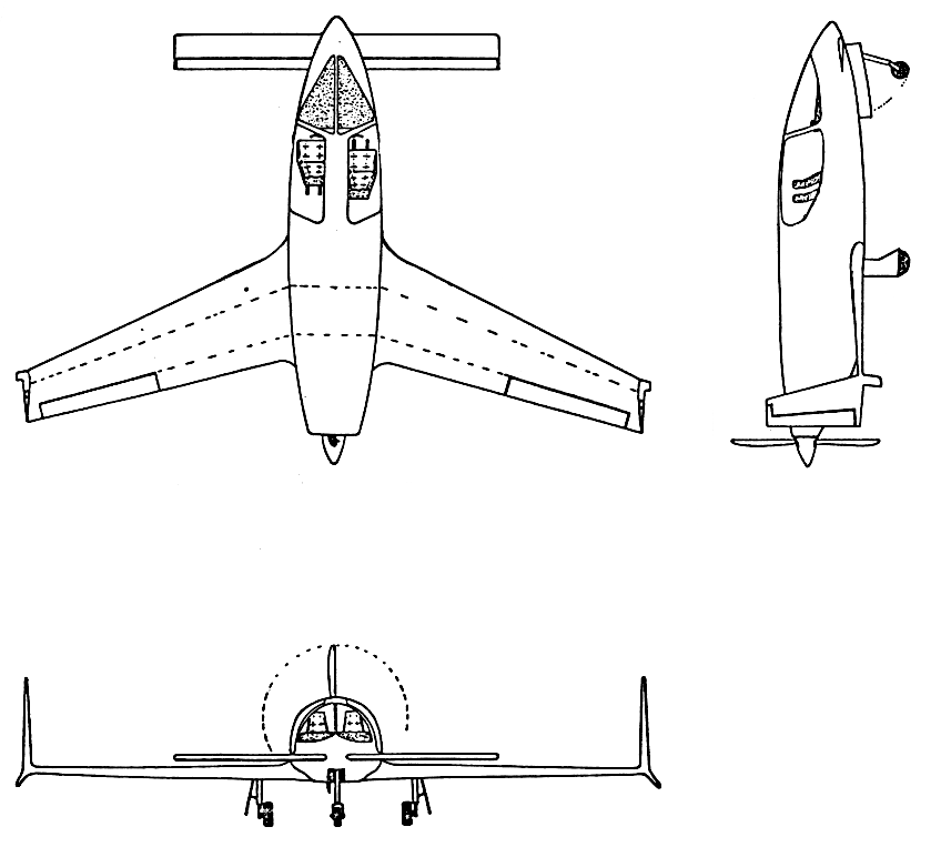 Figure 1: Three view drawing of the ‘YAKA’ project. |
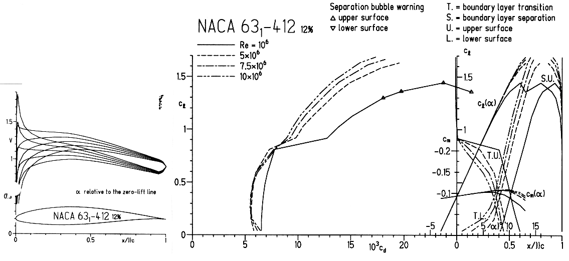 Figure 2: Velocity distributions and drag polars of NACA 631-412, smooth surface. |
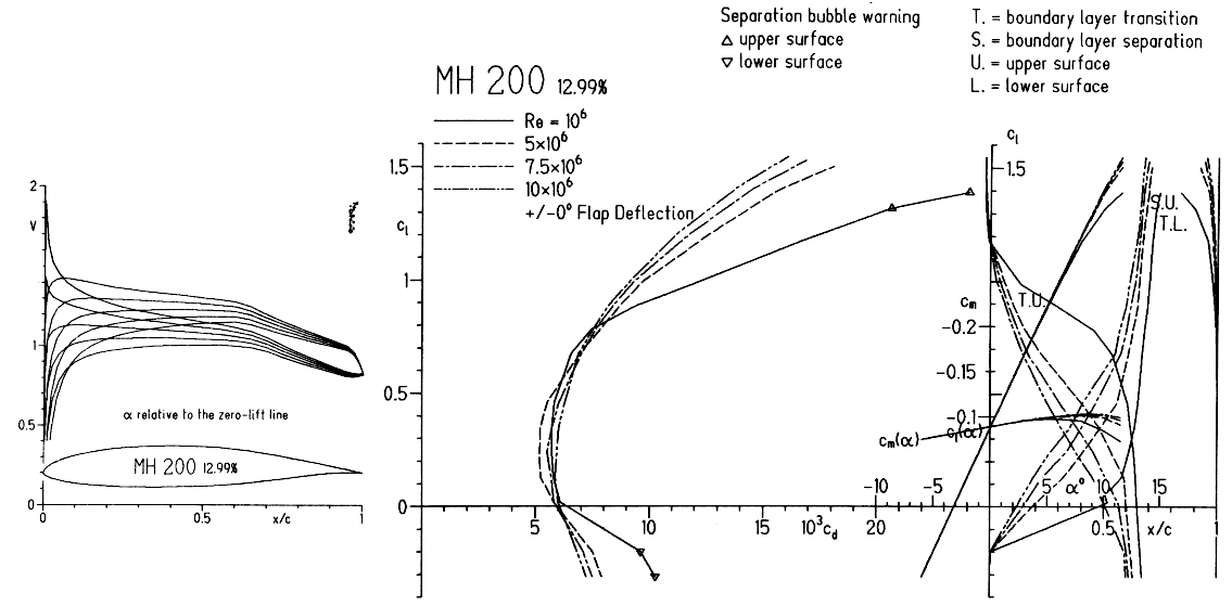 Figure 3: Velocity distributions and drag polars of MH 200, smooth surface. |
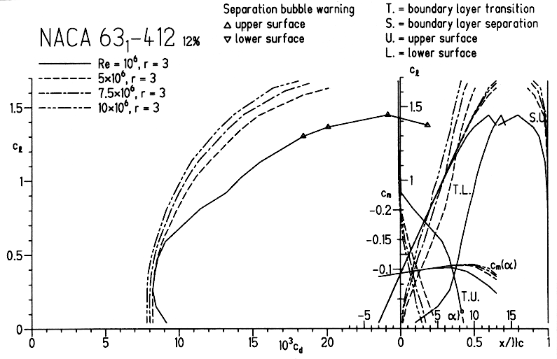 Figure 4: Drag polars of NACA 631-412, rough surface. |
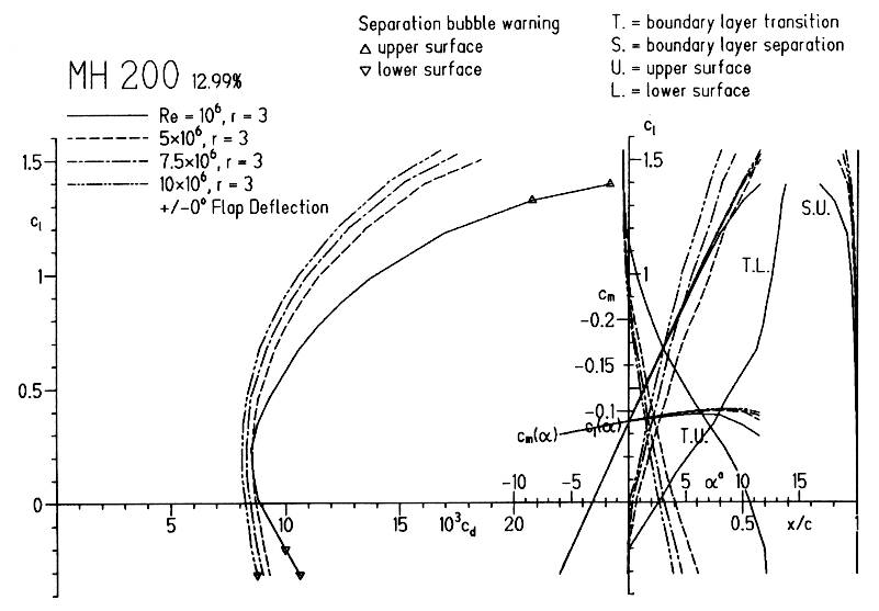 Figure 5: Drag polars of MH 200, rough surface. |
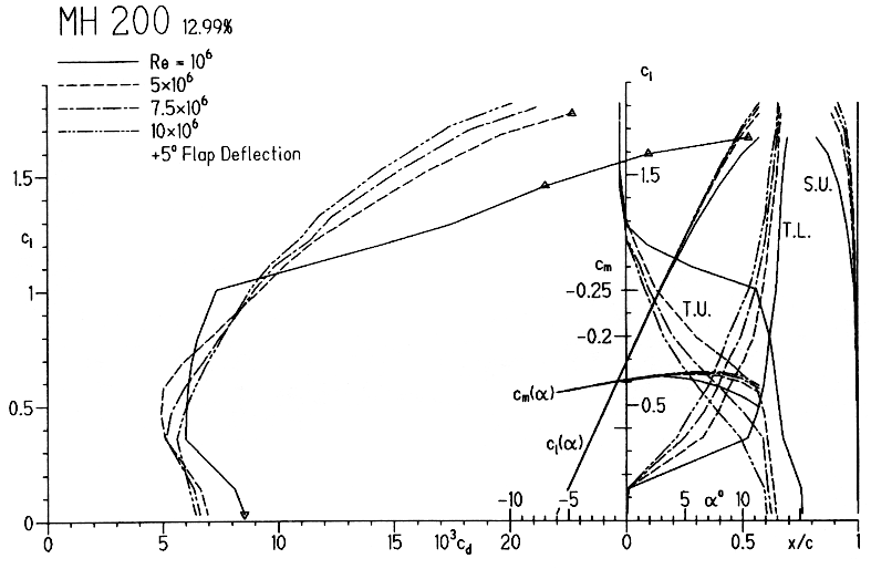 Figure 6: Drag polars of MH 200 with a flap deflection of +5°, smooth surface. |
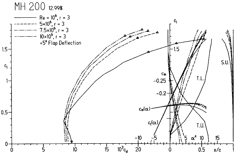 Figure 7: Drag polars of MH 200 with a flap deflection of +5°, rough surface. |
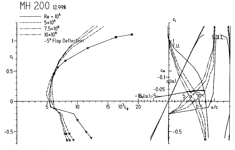 Figure 8: Drag polars of MH 200 with a flap deflection of -5°, smooth surface. |
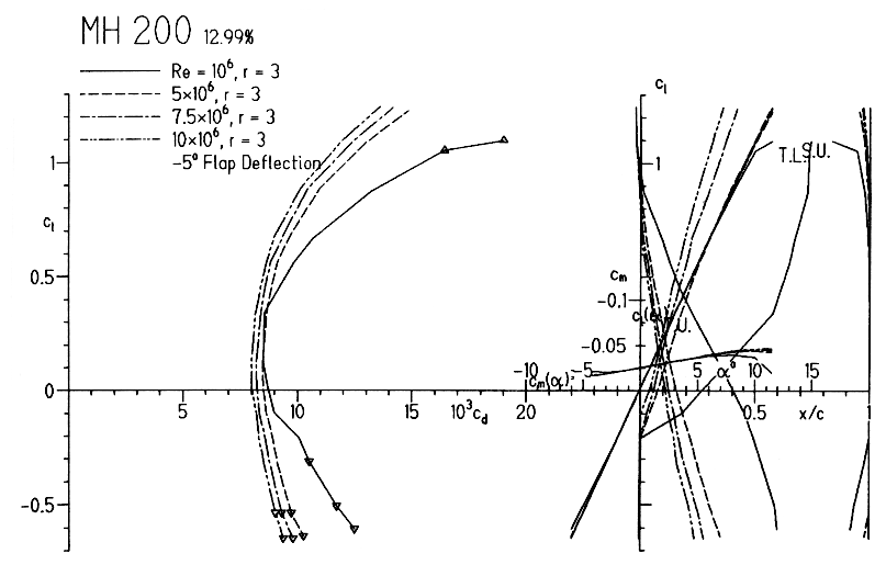 Figure 9: Drag polars of MH 200 with a flap deflection of -5°, rough surface. |
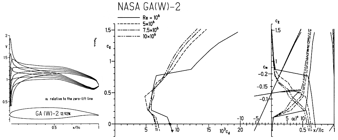 Figure 10: Drag polars of NASA GA(W)-2, smooth surface. |
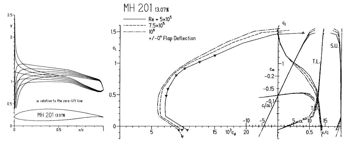 Figure 11: Drag polars of MH 201, smooth surface. |
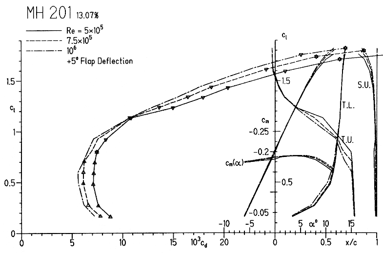 Figure 12: Drag polars of MH 201 with a flap deflection of +5°, smooth surface. |
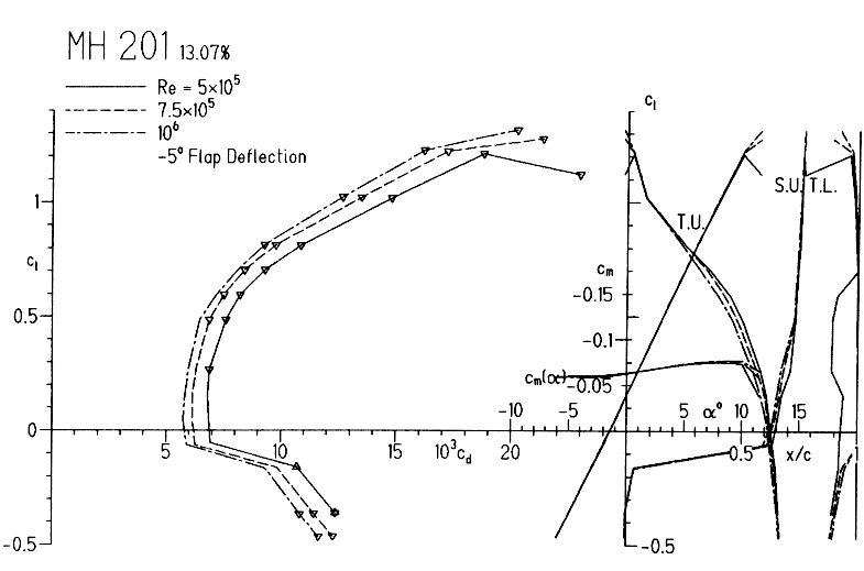 Figure 13: Drag polars of MH 201 with a flap deflection of -5°, smooth surface. |
| On this page |
|
Go to new page |
|