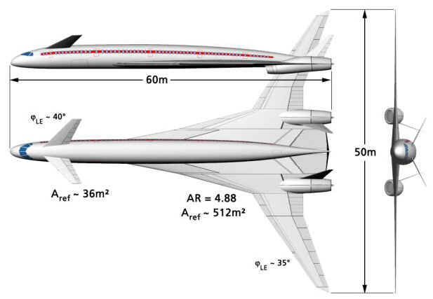
Figure 1: Three-view-drawing
of the configuration composed for the concept analysis.
International Symposium "Aviation Technologies of the XXI Century: New Aircraft Concepts and Flight Simulation", 7-8 May 2002 Aviation Salon ILA-2002, Berlin
Dr. Martin Hepperle
DLR Institute of Aerodynamics and Flow Technologies, DLR Braunschweig, Germany
Early in 2001 the Boeing company announced a new aircraft, the “Sonic Cruiser”. The most impressive features of this new project were a range of up to 10’000 nautical miles, a cruise Mach number above M = 0.95 and the claim of a large reduction in flight time.
A concept level study was undertaken to design and analyze a possible aircraft configuration. One result of the study is the fact, that the reduction of flight time by increasing the cruise Mach number to M = 0.98 is relatively small. A larger reduction of travel time seems to be possible only by using direct point to point services instead of hub and spoke connections. Another result is, that the claimed range would be very hard to reach.
|
Symbol |
Description |
Units |
|
Symbol |
Description |
Units |
|
r |
density of air |
[kg/m³] |
|
AR |
aspect ratio |
[-] |
|
|
|
|
|
G |
weight |
[N] |
|
e |
Oswald factor |
[-] |
|
H |
altitude |
[m] |
|
b |
wing span |
[-] |
|
R |
range |
[m] |
|
g |
gravity acceleration |
[m/s²] |
|
S |
wing area |
[m²] |
|
m0 |
take off mass |
[kg] |
|
CD |
drag coefficient |
[-] |
|
m1 |
landing mass |
[kg] |
|
CD,i |
ind. drag coefficient |
[-] |
|
mFuel |
fuel mass |
[kg] |
|
CL |
lift coefficient |
[-] |
|
|
|
|
|
TSFC |
spec. fuel consumption |
[1/h] |
|
|
|
|
|
BPR |
bypass ratio |
[-] |
The year 2001 saw the Airbus company going ahead with the final development of the A-380 large capacity aircraft. At the same time the Boeing company shelved its plans for the 747X and announced a new aircraft family operating at Mach numbers above M = 0.95. The impressive features of this project as claimed by Boeing were an extremely high range of up to 10’000 nautical miles, a high subsonic cruise Mach number and a reduction in flight time of 1 hour per 3’000 nautical miles flown.
The concept poses interesting aerodynamic and structural challenges. The analysis results show that the flow around large portions of the aircraft will be supersonic, even if very thin airfoil sections are used. The thin wings will also require a well designed structural concept to achieve the required weight and stiffness. The adaptation and the integration of the jet engines and their fuel consumption is another key issue for the success of the configuration.
In order to assess the feasibility of such an airplane, a concept level study was undertaken to analyze a possible aircraft design which was based on the available information about the Boeing configuration. While the name “Sonic Cruiser” is used in this paper, the results of the analysis as described in this paper may or may not be close to the real Aircraft.
Initially it was difficult to collect technical information and data about the concept. Main sources of information were the Boeing internet pages and articles in aerospace magazines. Additional information could be drawn from Boeings press releases and presentations at the Paris air show [1], [2], [3], [4], [5], [6], [7], [8]. It is interesting to note, how some technical data developed over time from wishful thinking to more realistic values. Especially the range performance has shrunk down to a more feasible number as shown in table 1.
|
Date |
Range |
Seating |
Altitude |
|
April 02, 2001 |
> 9’000 nmi |
100 - 300 |
> 40’000 ft |
|
February 11, 2002 |
6’000 … 7’500 nmi |
200 - 250 |
> 40’000 ft |
|
Source: http://www.boeing.com/news/feature/concept/facsheet.html |
|||
Table 1: Comparison of published mission data.
Mainly based on Boeings artists impressions and some published technical data like approximate wing span, fuselage length and diameter it was possible to create a first design sketch of the aircraft. The general layout and the aircraft sizing was performed according to methods described in [10], [11] and [12]. The characteristic canard configuration with engines buried in the wing and twin fins used for the analysis is shown in figure 1. For the redesign a small capacity of about 200 passengers has been assumed which seems to make sense for a point to point connection concept.
Figure 1: Three-view-drawing
of the configuration composed for the concept analysis.
A comparison of the configuration with existing transport aircraft is presented in figure 2 and table 2. On the one hand the Concorde offers a much higher cruise speed at the cost of a small passenger capacity, short range and high fuel burn. On the other hand, a typical airliner like the DC-10 operates very economically carrying a similar number of passengers as the Sonic Cruiser but at lower cruise Mach numbers. It is clearly visible, that the Sonic Cruiser has a much wider fuselage than the supersonic Concorde. Its wing span is larger than that of a DC-10, but as a tribute to the higher design Mach number its fuselage is more slender.
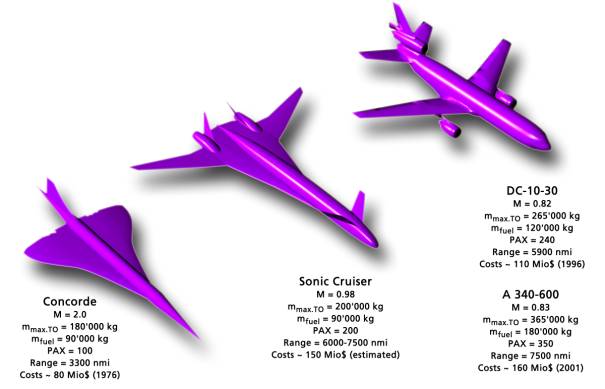
Figure 2: The Sonic Cruiser between a Concorde and a DC-10-30 (identical scale).
|
Parameter |
Sonic Cruiser |
B 767-200ER |
B 777-200-IGW |
|
Cruise Mach Number |
0.96 |
0.80 |
0.82 |
|
Passengers |
200 |
181 |
305 |
|
Wing Span |
50.0 m |
47.6 m |
60.9 m |
|
Overall Length |
60.0 m |
48.5 m |
63.7 m |
|
Fuselage Width |
5.1 m |
5.0 m |
6.2 m |
|
Reference Area |
512 m² |
283 m² |
428 m² |
|
Range |
6’500 nmi |
6’600 nmi |
7’150 nmi |
|
Initial Cruise Altitude |
40’000 ft |
35’000 ft |
34’100 ft |
|
Max. T-O Mass |
» 200’000 kg |
175’500 kg |
286’895 kg |
|
Max. Fuel Mass |
» 90’000 kg |
73’600 kg |
135’845 kg |
Table 2: Comparison of a Sonic Cruiser with Boeing 767 and 777 data.
In order to facilitate the following analysis work, a surface modeling tool was used to build a detailed three dimensional model of the configuration. This model (see figure 3) was used to examine geometric details like cabin layout, engine integration and tank volume. Later, the surface was used to build a grid for the analysis of the transonic flow field using an Euler solver. The following sections describe the main components of the aircraft and their features.
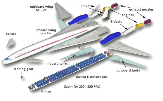
Figure 3: Exploded view of the Sonic Cruiser showing the main components and details.
Initially, a streamlined shape without a cylindrical center section was selected for the fuselage to keep the transonic drag low. Later, the center portion of the fuselage was replaced by a cylindrical part with a smooth transition between the cabin part and the cockpit area respectively the tail cone to keep wave drag low.
The diameter of the cabin has been kept at a minimum which allows for a twin aisle 2-2-2 or 2-3-2 seating arrangement (see figure 4). The diameter was chosen so, that it possible to carry two typical LD-3 containers side by side which requires a minimum diameter of 5.1 meters. Seating could be arranged so that 25 first class seats are available and the remaining seats can be used for a mixed business / economy class seat arrangement as needed. Boarding would be behind the canard, with the main entrance/exit separating first class and business class. The placement of emergency exits according to FAR guidelines poses no problems, but all rear exits will be located over the inboard wing.
In order to avoid velocity peaks in the cockpit area, the flat windscreen windows have been aligned with the fuselage body as far as possible. To ensure the required visibility angles, the windows would have to be larger than usual.
The canard wing was mounted high to achieve enough cabin height to access the first class compartment and the cockpit area. The dihedral of the canard was initially copied from the publications and would help to avoid collision with ground equipment. On the other hand it is not possible to establish sufficient lateral stability with the large angle of dihedral and the small tail fins so that we can assume a small dihedral close to zero degrees.
From a structural point of view, the fuselage must sustain the somewhat higher pressure differential due to the increased flight altitude and it must provide enough stiffness to carry the loads of the canard wing. The inboard wing extensions may provide additional stiffness to the fuselage and can carry a large portion of the fuel.
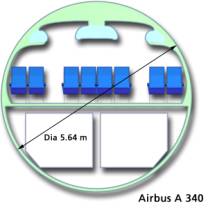
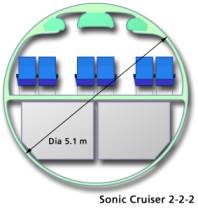
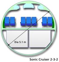
Figure 4: Typical Fuselage cross sections of an Airbus A 340 and the Sonic Cruiser with two possible seating arrangements.
The wing consists mainly of two parts: a highly swept center part with a kinked leading edge extending far forward along the fuselage side and the outboard wing with a lower amount of sweep. The wing span is similar to a Boeing 767, but the wing area is nearly twice as large. The additional wing area is mostly located in the inboard wing and helps to provide additional volume for the required fuel. It is also necessary to keep the lift coefficient at a reasonable level during the high altitude cruise. At the cruising speed of M = 0.98 the flow around the inboard wing can be kept subsonic if the airfoil thickness is below 3%. Due to the large wing chord this is possible while maintaining a root thickness of about 1.5 m. Even if the outboard wing is built up from an airfoil section of 5% t/c or even below, the flow will be supersonic in this region. An increase of the leading edge sweep angle from the selected value of 35° seems to be difficult from a structural point of view as well as with respect to stability and control at low speed. The low thickness of the wing will require a careful structural and aeroelastic design, very likely employing advanced materials like titanium and composite materials. The inboard wings can house about 2´45 m³ of fuel whereas the thin outboard wings can hold approximately 2´14 m³ in their spar box. Due to the long range mission, fuel must also be carried in the wing center box inside the fuselage. The total fuel volume amounts to 118 m³ or about 90 tons without counting any trim tanks in the canard or in the fuselage.
Besides the canard, the engine installation is another unique feature of the configuration. Both engines are buried in the wing so that no pylons are necessary. The exhaust nozzle is located behind the trailing edge of the wing, which eliminates jet interference. The flow to the fan is directed from the pitot style inlet at the lower wing surface through an S-shaped duct. By optimizing the duct shape, inlet losses and flow distortion as well as the fan noise can be minimized. In order to provide enough thrust at the high cruise Mach number, a lower bypass ratio was assumed. The reduced fan diameter also improves the transonic drag of the engine installation. The engine could be developed from an existing engine core like the GE 90 or the P&W 4084. Besides a new fan design the exhaust system has to be adapted to the cruise Mach number and also a new design of the thrust reversing system would be required. The lower BPR has the disadvantage to increase the thrust specific fuel consumption and the higher jet velocity increases the noise level. The analysis was based on an engine, which was developed using procedures described in [9]. The most important engine data are listed in table 3. The required static thrust is driven mainly by the thrust requirement at takeoff with one engine inoperative. In cruise, the engine runs at 60% thust setting.
Parameter |
H = 0 m M = 0 |
H = 15 km M = 0.98 |
Unit |
|
Fan Diameter |
3.1 |
[m] |
|
|
Core Diameter |
1.0 |
[m] |
|
|
Nozzle Diameter |
2.1 |
[m] |
|
|
Length |
7.4 |
[m] |
|
|
Mass |
8’500 |
[kg] |
|
|
BPR |
6.0 |
[-] |
|
|
Thrust |
435 |
70 |
[kN] |
|
Thrust Specific Fuel Consumption |
0.51 |
0.667 |
[1/h] |
Table 3: Data for the fictive low BPR engine.
Considering the well known range equation for an aircraft powered by jet engines (1) it is obvious that the maximum range for a given amount of fuel is obtained if a design achieves a high aerodynamic efficiency, operates at high altitude, has a low wing loading and a low fuel consumption.
 (1)
(1)
The density r of the air decreases rapidly when the altitude is increased: at an altitude of 12 km it is approximately 25% and at 15 km only 15% compared to sea level. On the other hand the velocity of sound decreases with altitude below 10 km only, which means that for a given design Mach number the actual flight speed reduces. Above 10 km the flight speed for a given Mach number changes only marginally. At 15 km the speed of sound is approximately 87% of the sea level value. Flying at M = 0.98 results in a flight speed of 1041 km/h which is nearly 20% faster than an airliner flying at H = 12 km and M = 0.82 (871 km/h).
As no detailed structural model was developed, the mass of the aircraft and its components was calculated using classical concept level methods. Compared to traditional aircraft, a penalty was assumed for the thin wing and the canard. Table 4 lists the mass distribution for the individual parts of the aircraft. As mass is crucial for the long range operation, advanced materials are likely to be used for the fuselage and a large portion of the wing.
Component |
Percentage |
Mass |
|
Wing |
16 % |
36 to |
|
Canard + Fins |
2 % |
4 to |
|
Fuselage |
8 % |
20 to |
|
Landing Gear |
3 % |
7 to |
|
Systems |
7 % |
17 to |
|
Engines + Nacelles |
13 % |
32 to |
|
Fuel |
39 % |
89 to |
|
Passengers |
12 % |
26 to |
|
Total |
100 % |
231 to |
|
Fuel-Fraction |
mfuel / m0 = 0.385 |
|
Table 4: Distribution of aircraft mass.
Due to the high cruise Mach number, aerodynamics plays an even more important role for this airplane than for conventional airliners. During the sizing process of the configuration, simple concept level aerodynamics procedures were used to determine lift and drag. For the wave drag, a refinement of these methods became necessary.
Friction Drag
Friction drag was based on local Reynolds number, assuming fully turbulent flow.
Induced Drag
The induced drag was calculated using the standard approximation with a variable Oswald factor “e” to represent the generation of vortex lift at higher angles of attack during take off and landing. A comparison with results of a panel code supported these results.
![]() (2)
(2)
Wave and Interference Drag
The calculation of the wave drag was initially based on concept level slender body theory, assuming an optimized volume distribution. Figure 5 shows the local cross section of the CAD model. The canard wing can be integrated smoothly into the distribution, but the rear part of the fuselage with engine nacelles and wing must be optimized as a single unit.
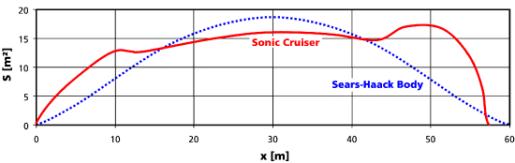
Figure 5: Cross section area distribution of the Sonic Cruiser configuration.
As it was not sure how accurate the predictions for the wave drag were, it was decided to perform a more elaborate analysis of the aerodynamics at high subsonic Mach numbers. Therefore the flow around the configuration was analyzed with the DLR flow solver “Tau” in Euler mode using an unstructured grid based on the CAD model. Thus we arrived at a better prediction for the wave drag for cruise speeds approaching M = 1. The Euler results indicate that a drag rise of DCD/DM = 0.1 occurs when M = 0.94 is reached. Figure 6 shows the drag rise and the L/D ratio versus Mach number. The typical cruise CL is between 0.4 and 0.5, yielding an L/D of 15 to 16. This value is probably somewhat conservative as the engine integration has not been optimized yet. The contribution of the individual components to the total drag for three different Mach numbers is presented in figure 7.
Figure 8 presents a typical Mach number distribution on the surface as well as a section cut through the outboard wing. It is clearly visible, that the flow around the canard and the outboard wing is completely supersonic, even with thin airfoils. A smaller supersonic region is caused by the nacelle/fin integration and can be reduced by careful refinement of the geometry. The Mach number on the fuselage and the inboard wings does not exceed M = 1.1 over most of their surface.
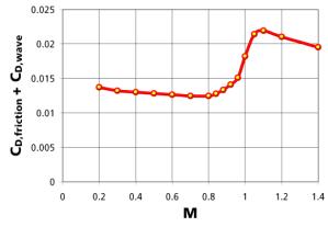
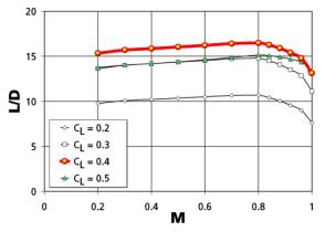
Figure 6: Drag coefficient (excluding induced drag) versus Mach number (left) and lift to drag ratio (right) for cruise at H = 15 km.
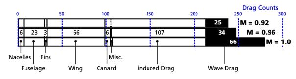
Figure 7: Drag Components for different cruise Mach numbers.
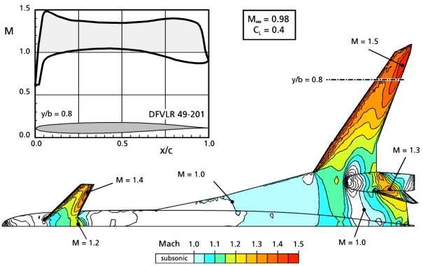
Figure 8: Distribution of the local Mach number on the upper surface of the Sonic Cruiser. The outboard wing section shows local Mach numbers up to M = 1.5.
Based on the analysis it is possible to plot the flight envelope depicted in figure 9. The typical lift coefficient is about CL = 0.48 during cruise at M = 0.98 and H = 15 km. The envelope also shows, that any additional increase in cruise altitude rapidly drives the lift coefficient towards the buffet and stall boundaries.
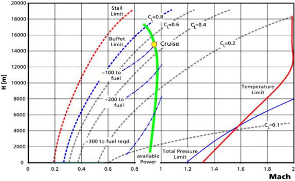
Figure 9: Calculated flight envelope including lines of constant lift coefficient and fuel consumption.
The analysis also shows that the required takeoff and landing performance of the aircraft can be met with simple high lift devices. At higher angles of attack, the lift of the inboard wing is augmented by leading edge vortices. The outboard wings may be equipped with a simple droop nose device instead of slats to avoid flow separation at high angles of attack. The landing distance is relatively short due to the large wing area.
|
Parameter |
Takeoff |
Landing |
Unit |
|
m/m0 |
1.0 |
0.73 |
[-] |
|
CL |
1.65 |
1.66 |
[-] |
|
vtakeoff resp. vtouchdown |
157 |
111 |
[kts] |
|
FAR Distance |
2100 |
1710 |
[m] |
Table 5: Takeoff and landing performance.
Combining the aerodynamic data, the structure/fuel mass ratio, the tank volume and taking the fuel consumption into account, a range of 6’500 nautical miles is just reachable when flying at M = 0.98. To extend the range to 7’500 miles, the TSFC of the engines must be reduced from 0.67 to about 0.55 in cruise, which seems to be possible. A further extension of the range to 9’000 miles would require engines operating with a TSFC of less then 0.55, which seems not to be feasible, at least not with a BPR below 8.
The main goals of the Sonic Cruiser design are a remarkable reduction of flight time and its long range. The concept offers interesting engineering challenges and a very narrow design space.
Flight Time
Compared to current designs, the pure cruise time reduction due to a high cruise Mach number of M = 0.98 is up to 20%. The difference of 20% reduces the flight time for 3’000 nmi from 6.3 to 5.3 hours. As this number will be reduced by the takeoff and landing as well as the climb and descend mission segments, this gain can only be realized, if the aircraft can climb and descend faster than the average air traffic. Additionally the concept to reduce travel time works only if point to point connections are used. This mission technique can be applied to “conventional” aircraft too. A more considerable cruise time reduction could be achieved by developing a supersonic aircraft, flying at M = 1.2 to 1.4, but at a considerable cost in range.
Range
Long range cruise at high Mach numbers requires engines with a fuel consumption in the order of the high bypass ratio engines of today. Based on current engine technology, a range of up to 7500 nautical miles seems to be possible, if the structural weight of the aircraft is minimized by extensive use of technologies like composite materials. On the other hand, the transonic aerodynamic performance must be very carefully optimized to reach an L/D ratio of at least 15 at M = 0.98.
Noise and Environment
The aircraft will make a steeper climb angle possible, which could be used to reduce the size of the noise footprint. According to Boeing this effect will not be consumed by the higher jet velocity of the low BPR engines. If a large number of these aircraft operate at high altitude, their exhaust emissions are accumulated in a region where only a reduced amount of natural convection exists. Consequently the environmental impact of the operation has to be carefully checked.
[1] http://www.boeing.com/news/feature/concept/
[2] Flight International 3, April 9, 2001
[3] Aviation Week and Space Technology, April 2, 2001
[4] Aviation Week and Space Technology, April 23, 2001
[5] Aviation Week and Space Technology, June 11, 2001
[6] Aviation Week and Space Technology, June 18, 2001
[7] Flug Revue, June 2001
[8] http://www.aviationweek.com/shownews/01paris4/hardwr09.htm
[9] Jack D. Mattingly: “Elements of Gas Turbine Propulsion”, McGraw-Hill, 1996.
[10] John D. Anderson: “Aircraft Performance and Design”, McGraw-Hill, 1999.
[11] Daniel P. Raymer: “Aircraft Design: A Conceptual Approach”, AIAA Education Series, 2nd printing, 1992
[12] Egbert Torenbeek: “Synthesis of Subsonic Airplane Design”, Delft University Press, 1982