![]()
![]()
Coordinates are a method to describe the shape of objects by numbers. When you have got a set of coordinates, you can re-create the object from these data. Airfoils are rather simple objects, as they are nothing but a curve, drawn on on a flat plane (e.g. a sheet of drawing paper or wood). Airfoil coordinates are usually given in two columns, called x and y. They describe an airfoil by single points and each point is defined by a pair of x-y coordinates. The airfoil can be made up from 50 or 100 points, which mean 50 to 100 coordinate pairs. As the designer of an airfoil does not know, how large the airfoil will be on your real wing, he must select an arbitrary airfoil size. Usually a chord length of 1.0 units or 100.0 units is used (the latter can be understood as percent of the wing chord, if you like). The units are of no importance, as the airfoil has to scaled to the desired size anyway.
To draw a basic airfoil shape, lets start with a set of coordinates, without scaling them first. My example coordinates are taken from the MH 42 airfoil, which used a standard length of 100.0. Lets assume, that we want to draw the airfoil with a chord length of 100.0 mm. The chord length is the length of the airfoil, measured from the leading edge to the trailing edge.
It is convenient to use a drawing paper with grid lines in millimeters. First we must define a reference system by drawing a horizontal line, called the x-axis. Then we draw another straight line, perpendicular to the x-axis, which intersects the x-axis on its left. This line is called the y-axis, and it is directed upwards. The x-axis should have a length of at least 100 mm.
For the next steps, it is convenient to divide and label the axis with subdivisions of 10 mm. We mark these divisions by short vertical lines on the x-axis and label them 0, 10, ... , up to 100. The y-axis can be shorter and will be labeled from 0 to 20. We should also extend the y-axis somewhat below the x-axis and label the divisions there with negative y-values (-10, -20). By using negative values for the y-axis, we have already established the direction of the y-axis: positive sign means upwards, negative numbers go downwards. We can add arrow heads to the positive ends of the axis to indicate their direction.
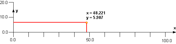
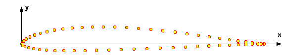
After having set up a coordinate system, consisting of x- and y-axis and their direction, we can start to draw the coordinate points. usually we plot the points in the order in which they are tabulated. Here I am just picking one coordinate pair from the middle of the set, namely the pair x=48.221 / y=5.987. First we will locate the x-coordinate. We measure 48.221 mm from the origin to the right and draw a vertical line, crossing the x-axis at x=48.221 (of course you will need very good eyes to mark the 1/1000 millimeters, but you will surely try to do your best, won't you?). Thus we know, that the point must be somewhere on this vertical line - but where should it be located? Ah well, we still have not made use of the second number, the y-coordinate! We find the location of the point by moving 5.987 mm from the x-axis, upwards on the vertical line. Or we start over at the y-axis (left side of the axis system), measure upwards and draw a horizontal line to the right, which intersects our vertical line. Both methods define the same point on the airfoil. The figure above shows this point in yellow and both construction lines in red. Performing the same procedure for all points in the coordinate set leaves us with a sprinkle of dots on the sheet, which make up the airfoil, as shown in the figure below.
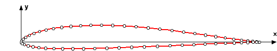
The final step is to connect the dots by a smooth line. This sounds easier than it is, as the resulting curve should be smooth and should have no kinks or bends. A flexible ruler (a spline) made from plastic material or thin wood helps to draw the shape of the airfoil. The result should look similar to the next figure below.
After building wings with 100 mm chord lengths for years, we might want to
build one with a chord length of 150 mm one day. To use the given set of
coordinates, we have to scale them accordingly. Well, being a rocket scientist
would probably help us here, but as that don't impress Shanya Twain much, we'll
try to do our very best again, counting with our fingers or using a pocket
calculator.
First we determine the scale factor: we need for a larger airfoil, namely
150/100 = 1.5 times as large. Using the calculator, we multiply all coordinate
pairs (x- and y-values) by 1.5, finally ending up with a set of airfoil
coordinates for a chord length of 150 mm. A simpler method would be to slap our
100 mm airfoil drawing on a photocopier, push the enlarge button, dial in
"150%" and press the "Copy" button (check the copier for
distortion first, by copying a sheet with grid lines).
While it is very instructive to drawn an airfoil or two manually, it is quite cumbersome to draw all sections for an elliptical wing by hand.
Maybe we can use one of these dumb computers (dude inside) to perform the hard work for us? Well, after patting myself on the shoulder for this brilliant idea, I had to discover, that there are already several computer programs out, which can scale airfoils, plot them, even with sheeting and spars. Also, my Concord airfoil coordinate converter can convert between various airfoil data file formats to help our poor computer to make a sweet, juicy airfoil out of those dry numbers [see my pages Software for Download and Other Links of Interest].
Computers are also one of the reasons, why the coordinates are usually given so precisely, with umpteen digits behind the decimal: they are so dumb, that they insist in plotting a wiggle every time a point does not fall exactly on what they believe to be a nice curve.
Even if you don't have an airfoil plotting program, you can use a spreadsheet program like Microsoft Excel™ to scale the coordinates and plot them in the correct size (after fiddling around with scaling and distortion of the XY-graph). These programs usually offer an XY-Graph type, which can draw smooth curves through a sequence of points. You can also use these spreadsheet programs for all kinds of manipulation of the point data.
Last modification of this page: 21.05.18
![]()
[Back to Home Page] Suggestions? Corrections? Remarks? e-mail: Martin Hepperle.
Due to the increasing amount of SPAM mail, I have to change this e-Mail address regularly. You will always find the latest version in the footer of all my pages.
It might take some time until you receive an answer
and in some cases you may even receive no answer at all. I apologize for this, but
my spare time is limited. If you have not lost patience, you might want to send
me a copy of your e-mail after a month or so.
This is a privately owned, non-profit page of purely educational purpose.
Any statements may be incorrect and unsuitable for practical usage. I cannot take
any responsibility for actions you perform based on data, assumptions, calculations
etc. taken from this web page.
© 1996-2018 Martin Hepperle
You may use the data given in this document for your personal use. If you use this
document for a publication, you have to cite the source. A publication of a recompilation
of the given material is not allowed, if the resulting product is sold for more
than the production costs.
This document may accidentally refer to trade names and trademarks, which are owned by national or international companies, but which are unknown by me. Their rights are fully recognized and these companies are kindly asked to inform me if they do not wish their names to be used at all or to be used in a different way.
This document is part of a frame set and can be found by navigating from the entry point at the Web site http://www.MH-AeroTools.de/.