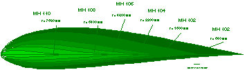
The airfoils MH 102 to MH 110 were part of the design of an optimum windmill. The windmill itself as well as the airfoils have been designed using direct inverse design methods.
Today, the design of horizontal axis windmills can be performed with good results, using inverse design methods, based on the minimum induced loss windmill, as defined by Glauert and Prandtl during the 1920s. For the analysis under off-design conditions, simple blade element methods and more complex vortex lattice methods lead to quite accurate results. The final blade geometry can be tailored exactly to the desired main operating range by using a suitable inverse design method for the airfoil sections.
 |
For a small horizontal axis wind turbine, the main project data were
proposed by the manufacturer, based on market studies. The basic
parameters of the windmill were a constant speed generator which could be
switched between two velocities of rotation and that the blade angle
should be constant and not adjustable. A gearbox between power generator
and the rotor of the windmill permitted the decoupling of aerodynamics and
the power generator.
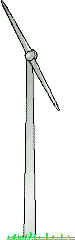
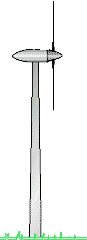
To avoid destruction of the windmill due to over speed caused by high wind speeds, it was decided to direct the aerodynamic layout towards a stall regulated machine. (such a windmill has no variable pitch blades to control the mill at higher wind speeds; instead, the airfoils are designed to stall sharply when the operating limits are exceeded, thus limiting the power output). After some preliminary design studies, the parameters for the design, as listed below, were selected. |
| Technical Data | ||
| diameter | 16 m | |
| gear 1 | gear 2 | |
| rotor speed | 80 1/min | 120 1/min |
| at wind speed | 6.0 m/s | 9.0 m/s |
| tip Mach number | 0.2 | 0.3 |
| power loading | 450 W/m² | |
| max. power output | 90 kW | |
| useful wind speed range | 5 <v <14 m/s | |
| stall controlled, fixed pitch, no adjustable blade angle | ||
Regarding low manufacturing costs and competitive energy costs, the number of blades was limited to two. To achieve high yearly power on times, with short low power and non operating times, a specific power loading of 450 W/m² had been selected. A lower loading would increase the full power times, but was not possible due to a diameter restriction.
On the one hand, simple momentum theory correctly predicts maximum efficiency to occur at maximum diameter, but on the other hand the tip Mach number is directly proportional to the diameter for a fixed velocity of rotation. The tip Mach number was limited to 0.3, as a compromise between aerodynamics and noise constraints. Together with the available gearboxes, this lead to local Reynolds numbers of more than 500`000, which is sufficient to achieve high L/D ratios, which are essential for good performance.
The geometry of the blades is determined by the task to transform as much energy as possible from the incoming air flow into mechanical, respectively electric power. Thus the aerodynamic design of the windmill should fulfill the minimum induced loss principle. The basic aerodynamic design of the windmill was based on Glauerts optimum windmill theory, which was embedded into the framework of an existing general blade element code. This code uses two dimensional airfoil polars, which gives very good results for attached flow conditions. For cross checks, additional analysis runs were performed, using a vortex lattice code. During the preliminary design of the blades, the operating conditions for the local airfoil sections were defined in terms of Reynolds and Mach numbers as well as lift coefficient range. These conditions were used for the design of new airfoils, which were then used in the windmill design method to find the optimum blade shapes. Later additions to the code make it possible to account for the boundary layer of the ground by performing several analysis at different azimuthal blade positions.
 |
Besides the number of blades, the planform and the power loading, the
airfoil sections are of utmost importance for the performance of a
windmill. Here maximum L/D ratios are desired to maximize efficiency,
taking into account, that the surface of a wind turbine will not be
perfectly smooth during the whole life span of a windmill - the airfoils
should have good L over D values with rough surfaces too. For the special case of a fixed pitch windmill, the characteristics of the airfoils are controlling the power versus wind speed performance curve. To avoid over speed conditions, the maximum power of the windmill has to be strictly limited, which can be achieved by a specially designed family of airfoils. These airfoils feature a distinct, but not necessarily hard primary stall, which leads to a limitation of the maximum power of the windmill. To avoid noise and structural problems, the airfoils have been designed to have a soft post stall plateau, followed by a soft secondary stall. The five airfoils MH 102 to MH 110 make up the new family, which shows no dramatic sensitivity with respect to surface roughness throughout the operating range. Because the preliminary windmill design and analysis defined ranges for the lift coefficient and the Reynolds number, Epplers inverse design method was ideally suited for the design of these airfoil sections. |
| 1) | 2) | 3) | ||||
| r/R | c/R | r | c | ß | Xd | Airfoil |
|---|---|---|---|---|---|---|
| [-] | [-] | [mm] | [mm] | [°] | [mm] | |
| 0.000 | 0.0000 | 0.0 | 0.1 | 84.500 | . | . |
| 0.040 | 0.1162 | 320.0 | 930.0 | 38.050 | . | . |
| 0.080 | 0.1094 | 640.0 | 875.1 | 25.844 | 271 | MH 102 |
| 0.120 | 0.0988 | 960.0 | 790.4 | 17.883 | . | . |
| 0.160 | 0.0917 | 1280.0 | 733.8 | 12.686 | . | . |
| 0.200 | 0.0890 | 1600.0 | 711.9 | 9.077 | 214 | MH 102 |
| 0.240 | 0.0842 | 1920.0 | 673.3 | 6.678 | . | . |
| 0.280 | 0.0814 | 2240.0 | 651.4 | 4.901 | . | . |
| 0.320 | 0.0783 | 2560.0 | 626.6 | 3.540 | . | . |
| 0.360 | 0.0745 | 2880.0 | 595.9 | 2.471 | . | . |
| 0.400 | 0.0717 | 3200.0 | 573.3 | 1.612 | 134 | MH 104 |
| 0.440 | 0.0689 | 3520.0 | 551.4 | 1.110 | . | . |
| 0.480 | 0.0668 | 3840.0 | 534.8 | 0.725 | . | . |
| 0.520 | 0.0653 | 4160.0 | 522.6 | 0.435 | . | . |
| 0.560 | 0.0643 | 4480.0 | 514.1 | 0.219 | . | . |
| 0.600 | 0.0635 | 4800.0 | 508.3 | 0.061 | 115 | MH 106 |
| 0.640 | 0.0606 | 5120.0 | 485.0 | -0.207 | . | . |
| 0.680 | 0.0579 | 5440.0 | 463.4 | -0.436 | . | . |
| 0.720 | 0.0553 | 5760.0 | 442.7 | -0.631 | . | . |
| 0.760 | 0.0528 | 6080.0 | 422.1 | -0.794 | . | . |
| 0.800 | 0.0499 | 6400.0 | 399.4 | -0.938 | 89 | MH 108 |
| 0.840 | 0.0468 | 6720.0 | 374.7 | -1.061 | . | . |
| 0.880 | 0.0429 | 7040.0 | 342.9 | -1.158 | . | . |
| 0.920 | 0.0371 | 7360.0 | 297.1 | -1.247 | . | . |
| 0.960 | 0.0280 | 7680.0 | 223.9 | -1.316 | 46 | MH 110 |
| 1.000 | 0.0000 | 8000.0 | 50.0 | -1.377 | . | . |
Table 2: Blade Geometry
The figure below shows the power delivered by the windmill at the two velocity of rotation settings. The lower 80 rpm value is used to start up the windmill and for wind speeds up to 8 m/s, whereas the 120 rpm setting is used for wind speeds between 8 and 14 m/s. The design power of 90 kW is reached at a wind speed of 13 m/s. For comparison, the chart also contains the power curve of a windmill using conventional airfoil sections, which result in a undesired power output at higher wind speeds.

Performance chart of the optimum stall controlled windmill.
Last modification of this page: 21.05.18
![]()
[Back to Home Page] Suggestions? Corrections? Remarks? e-mail: Martin Hepperle.
Due to the increasing amount of SPAM mail, I have to change this e-Mail address regularly. You will always find the latest version in the footer of all my pages.
It might take some time until you receive an answer
and in some cases you may even receive no answer at all. I apologize for this, but
my spare time is limited. If you have not lost patience, you might want to send
me a copy of your e-mail after a month or so.
This is a privately owned, non-profit page of purely educational purpose.
Any statements may be incorrect and unsuitable for practical usage. I cannot take
any responsibility for actions you perform based on data, assumptions, calculations
etc. taken from this web page.
© 1996-2018 Martin Hepperle
You may use the data given in this document for your personal use. If you use this
document for a publication, you have to cite the source. A publication of a recompilation
of the given material is not allowed, if the resulting product is sold for more
than the production costs.
This document may accidentally refer to trade names and trademarks, which are owned by national or international companies, but which are unknown by me. Their rights are fully recognized and these companies are kindly asked to inform me if they do not wish their names to be used at all or to be used in a different way.
This document is part of a frame set and can be found by navigating from the entry point at the Web site http://www.MH-AeroTools.de/.