The eXtensible Markup Language format (XML) is being used by many programs for almost all kind of data handling. In contrast to several other file formats, its main advantages are
I have defined an XML schema to represent the geometry of airfoils, which can be used to describe the geometry of single and multi element airfoil sections. It would be very helpful, if such a format would be implemented by most programs which handle airfoil coordinates. Life could be much easier, if there would be no need for conversion tools like my Concord program.
Any XML file is made up from tags similar to a HTML file. Tags are enclosed in pointed parentheses (<tag>). Each XML file must begin with a header tag:
<?xml version="1.0"?> |
Tags must occur in pairs - opening and closing tags must be paired. In contrast to HTML the names of the remaining tags are not prescribed, but can be defined by the user. To be useful for data transfer, the names of the tags must be known to and data receiver. Therefore an XML scheme can be set up, which describes the tag names and their content.
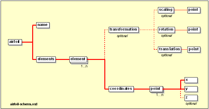
As tags can be nested, it is possible to create an object oriented representation of structured data quite well. For example an airfoil coordinate point consists of two items, namely the <x> and the <y> values. An airfoil shape in turn is made up of several coordinate points and a multi element airfoil may be composed of several airfoil shapes.
My XML airfoil schema is named "airfoil-schema" of course and is stored in an XML file "airfoil-schema.xsd". It describes the types of elements and their allowed contents. For example the coordinate values for "x" and "y" are declared to be of type "float" and each "point" consists at least of one "x" and "y" pair. A complete structured description of the schema and all its elements can be found here.
Now the schema looks quite complicated, but you shouldn't be too much impressed. The graph below shows a compact view of the structure described by the schema. The airfoil XML file packages the data items that make up the geometry at different levels. If we were only interested in the number of elements of a multi element airfoil, we don't have to dive down to the x-y coordinates, but descend only down to the <elements> collection and count its children (named <element>)

The example below should shed more light on the structure of an airfoil-XML file. As the XML file is nicely and hierarchically structured, it is relatively easy to write a very simple XML parser for these airfoil files. On the other hand professionally written parsers are available for many languages, including Java, C++, Fortran. Under MS-Windows the Microsoft COM component MSXML can be used with almost all languages. Before you start to write your own parser, I would highly recommend to examine the available parsers. These can handle unexpected conditions, a wild variety of formatting styles (indenting, line breaks) and often have the capability to validate a file against the schema. Thus you can validate a file before actually delving into its data tree to make sure that all required elements are there and contain valid data.
Writing an xml file is much easier, because you know what goes into the file and there are no unknowns.
<?xml version="1.0" encoding="ISO-8859-1"?>
<airfoil xmlns:xsi="http://www.w3.org/2001/XMLSchema-instance"
         xmlns="http://www.mh-aerotools.de/airfoil-schema"
         xsi:schemaLocation="http://www.mh-aerotools.de/airfoils/xml-schemas/airfoil-schema airfoil-schema.xsd">
 <!-- the previous lines describe the location of the schema document which defines the
      default "name space". These are used for validating the contents of the file.
      First the prefix "xsi" is defined to refer the elements defined in the
      "http://www.w3.org/2001/XMLSchema-instance" schema. This standard schema is usually
      embedded in all parsers, so no location must be given.
      Then the default namespace is defined to be "http://www.mh-aerotools.de/airfoil-schema".
      Finally the string assigned to "xsi:schemaLocation" links this namespace to the file
      "airfoil-schema.xsd". This is a location where the parser can find the schema
      description file. If it is in a different directory as the airfoil file, it would
      maybe read "./schemas/airfoil-schema.xsd".
      It could also be an URL like "http://www.mh-aerotools.de/airfoils/xml-schemas/airfoil-schema.xsd"
      if you prefer to access the document via the internet.
      -->
<name>MH 20</name>

<elements>
  <element>

    <transformation>
      <scaling>
        <point><x>1.0</x><y>1.0</y><z>1.0</z></point>
      </scaling>
      <translation>
        <point><x>0.0</x><y>0.0</y><z>0.0</z></point>
      </translation>
      <rotation>
        <point><x>0.0</x><y>0.0</y><z>0.0</z></point>
      </rotation>
    </transformation>

    <coordinates>
      <point><x>1.0000000</x><y>0.0000000</y><z>0.000</z></point>
      <point><x>0.9974300</x><y>-0.0000100</y><z>0.000</z></point>
      <point><x>0.9897699</x><y>0.0000700</y><z>0.000</z></point>
      <point><x>0.9770700</x><y>0.0005000</y><z>0.000</z></point>
      <point><x>0.9594799</x><y>0.0014100</y><z>0.000</z></point>
... a few points omitted (x-y-coordinates are mandatory, z can be omitted) <point><x>0.9770700</x><y>-0.0025500</y><z>0.000</z></point>
<point><x>0.9897699</x><y>-0.0010600</y><z>0.000</z></point>
<point><x>0.9974300</x><y>-0.0002400</y><z>0.000</z></point>
<point><x>1.0000000</x><y>-0.0000400</y><z>0.000</z></point>
</coordinates>
</element>
</elements>
</airfoil>
|
Remarks:

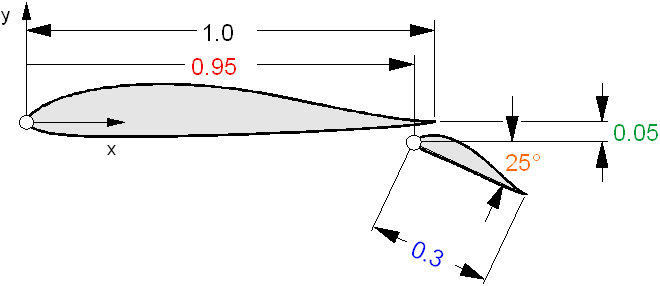
| Main Element, standard transformation | Flap element, scaled, rotated and translated |
<transformation> <scaling> <point><x>1.0</x><y>1.0</y></point> </scaling> <translation> <point><x>0.0</x><y>0.0</y></point> </translation> <rotation> <point><x>0.0</x><y>0.0</y><z>0.0</z></point> </rotation> </transformation> |
<transformation> <scaling> <point><x>0.30</x><y>0.30</y></point> </scaling> <translation> <point><x>0.95</x><y>-0.05</y></point> </translation> <rotation> <point><x>0.0</x><y>0.0</y><z>-25.0</z></point> </rotation> </transformation> |
Last modification of this page: 21.05.18
![]()
[Back to Home Page] Suggestions? Corrections? Remarks? e-mail: Martin Hepperle.
Due to the increasing amount of SPAM mail, I have to change this e-Mail address regularly. You will always find the latest version in the footer of all my pages.
It might take some time until you receive an answer
and in some cases you may even receive no answer at all. I apologize for this, but
my spare time is limited. If you have not lost patience, you might want to send
me a copy of your e-mail after a month or so.
This is a privately owned, non-profit page of purely educational purpose.
Any statements may be incorrect and unsuitable for practical usage. I cannot take
any responsibility for actions you perform based on data, assumptions, calculations
etc. taken from this web page.
© 1996-2018 Martin Hepperle
You may use the data given in this document for your personal use. If you use this
document for a publication, you have to cite the source. A publication of a recompilation
of the given material is not allowed, if the resulting product is sold for more
than the production costs.
This document may accidentally refer to trade names and trademarks, which are owned by national or international companies, but which are unknown by me. Their rights are fully recognized and these companies are kindly asked to inform me if they do not wish their names to be used at all or to be used in a different way.
This document is part of a frame set and can be found by navigating from the entry point at the Web site http://www.MH-AeroTools.de/.