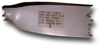
 The label on the blade of a DC-3 propeller lists the variable pitch range. |
 Commercial propeller measuring gauge. |
The propeller measuring gauge shown here, is a commercial product and has been sold by Prather Inc. some years ago. It is probably still sold, but I don't know the current distributor in the USA. The jig is specially designed for pitch measurements of propellers at different radial sections and the pitch can be read directly from its scales without further calculations. A drawback of the gauge is the fact, that the angle of the lower side of the section is measured, which is not exactly the aerodynamically relevant blade angle. If the relative thickness of all airfoil sections were the same along the radius and if all airfoils would have a flat lower side, then the error would simply be a constant offset from the nominal pitch angles. But the relative airfoil thickness and thus the camber varies from station to station which makes a propeller with an aerodynamically perfect constant pitch look like being incorrectly twisted when using this gauge. I would recommend to use it for quick checks of the global pitch only, but not for fine tuning of a propeller, if a specified pitch distribution is desired. The gauge is the only method, which can be used on the flying field for a quick comparison of different propellers. |
 The tracing method and it's tools. |
A relatively simple way to get the propeller geometry with
medium accuracy, is the non destructive tracing method. You
attach the propeller to a block so that its axis is perpendicular to a
flat table. Now you prepare some pieces of flexible cardboard, slightly
longer than the propeller radius - you need three sheets. Then you use a
water soluble felt tip pen and paint the leading edge of the propeller,
quickly place a cardboard sheet vertical on the table and press it against
the edge of the propeller, before the felt tip color has dried. Doing the
same at the trailing edge leaves you with two traces on the cardboard. You
should add markers to the boards to identify different radial sections.
Finally you need a graph of the planform of the prop, which is easily
created by holding the third cardboard sheet against the lower side and by
tracing the outline of the blade on the board with a pencil. Add some
markers for the same radial stations to this piece of art. Now you are ready for some simple trigonometric math (a programmable calculator comes in handy, but is not really necessary). It is recommended to make a small table with 5 columns for the chord length c, trailing edge height ht and the leading edge height hl, the trailing edge - leading edge difference dh and, the blade angle ß. For each radius station you
The trace of the trailing edge corresponds very precisely to the end of the airfoils x-axis, but the plot at the leading edge is slightly off (due to the leading edge radius of the airfoil). Theoretically the error depends on the leading edge radius and should be small - typically between 1 and 4 degrees. Remark: |
 A photograph of a cut through a 3 bladed propeller for F3A models (1985). |
Unfortunately an almost perfect method to measure the geometry of a propeller is destructive. The method is very simple: beginning at the tip, we cut a sample propeller at the radial station of interest, paint the cut white (for a carbon fiber prop) and take a photograph, including a pin in the axis of the propeller. A paper print or a slide can be used to measure the blade angle ß with respect to the axis as well as the airfoil shape or at least the maximum thickness and the camber. In fact it is even possible to get the airfoil coordinates quite accurately from such a photograph by scanning the image into a computer and redrawing the shape with spline curves. |
 A propeller blade for an ultra-light airplane and the matching set of templates. |
This method is very similar to the slicing method, but instead of cutting the propeller into pieces, small, flat templates are used, which are attached to the waxed surface of the propeller using quick setting polyester putty. These templates can then be photographed and dealt with as with the slicing method. If you have a computer and a flatbed scanner, you can use it to scan the templates instead of using photographs. The templates are made from plywood and should resemble the propeller section closely, leaving a small gap of about 2 millimeters only, which will be closed by the filler. They are made in two parts, so that they can be separated into an upper and a lower segment - the lower part must fit flush to the table to have a reference for the blade angle. This method has also been successfully applied to analyze full scale propellers and is quite accurate. |
  Comparison of the results obtained from the slicing and from the tracing method. |
A comparison of tracing and slicing method shows, that the
chord distribution can be measured quite accurately using the tracing
method - the error is around 1 percent of the propeller radius. Close to
the tip an extrapolation is recommended, if the tip has a rounded shape.
It should not be forgotten, that the chord length can be measured very
accurately with a conventional slide gauge.
The error in the blade angle of the tracing method can be larger than theoretically expected. Close to the tip, the tracing method claims blade angles which are about 4 degrees below the results of the slicing method. Close to the hub of the propeller, the deviation may be as large as 8 degrees. taking the leading edge radius into account reduces the error by 1 to 2 degrees. The main source for the error is probably the accuracy of the height measurements hl and ht, which could be improved by more careful work. Due to the small dimensions, an error of 0.5 mm can result in an blade angle error of several degrees. |
Where do you want to go now?
![]() Design a Prop
Design a Prop ![]() Optimum Propellers
Optimum Propellers ![]() How a Propeller works
How a Propeller works
![]() Equivalent Multiblade Propellers
Equivalent Multiblade Propellers
Last modification of this page: 21.05.18
![]()
[Back to Home Page] Suggestions? Corrections? Remarks? e-mail: Martin Hepperle.
Due to the increasing amount of SPAM mail, I have to change this e-Mail address regularly. You will always find the latest version in the footer of all my pages.
It might take some time until you receive an answer
and in some cases you may even receive no answer at all. I apologize for this, but
my spare time is limited. If you have not lost patience, you might want to send
me a copy of your e-mail after a month or so.
This is a privately owned, non-profit page of purely educational purpose.
Any statements may be incorrect and unsuitable for practical usage. I cannot take
any responsibility for actions you perform based on data, assumptions, calculations
etc. taken from this web page.
© 1996-2018 Martin Hepperle
You may use the data given in this document for your personal use. If you use this
document for a publication, you have to cite the source. A publication of a recompilation
of the given material is not allowed, if the resulting product is sold for more
than the production costs.
This document may accidentally refer to trade names and trademarks, which are owned by national or international companies, but which are unknown by me. Their rights are fully recognized and these companies are kindly asked to inform me if they do not wish their names to be used at all or to be used in a different way.
This document is part of a frame set and can be found by navigating from the entry point at the Web site http://www.MH-AeroTools.de/.