Smaller tailless airplanes, like ultra light and foot launched gliders should be designed with a larger safety margin regarding stall speed and stall behavior. Due to their low flight speed, the are responding lively to guests during the takeoff and landing phase, which may cause large angle of attack variations. Additionally they operate in a Reynolds number range between 200'000 and 1 million, where the boundary layer has a strong impact on airfoil performance and behavior.
First we will have a look at two existing airfoil sections, which have been used in man carrying tailless airplanes. The first one is a modern airfoil (FX 05-H-126) with a reflexed camber line, which was not designed for amateur built tailless planes, but for helicopter blades. Nevertheless it has been used in some amateur projects, by people seeking for maximum performance. The second airfoil (Horten II) has been designed for light tailless planes, but is much older, having been designed in the 1930s.
This airfoil has been designed by F. X. Wortmann during a stay at the Bell helicopter company in the USA.
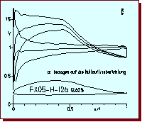
Velocity distribution of the FX 05-H-126 airfoil at 3 different angles of
attack.
The design point corresponds approximately to the middle of the three curves.
The velocity distribution shows a typical low speed laminar flow airfoil. The velocity on the upper surface increases steadily to 50% chord length, where a rather steep, concave velocity drop starts. The velocity on the lower surface is nearly constant, slightly increasing towards the trailing edge. Such a distribution results in laminar flow over the first half of the airfoils upper surface and along the total length of the lower surface. The drag polar, shown below, indicates the benefits and the problems of such a velocity distribution: very low drag and good performance, but only in a narrow range of lift coefficients (laminar bucket). Outside of the bucket, the drag increases rapidly and the danger of flow separation at low Reynolds numbers is quite high. The airfoil has a hard stall behavior and suffers from flow separation at Reynolds numbers below 2 millions. For an amateur built, light tailless glider, it is probably not a good choice (but well suited for the blade of a helicopter rotor).
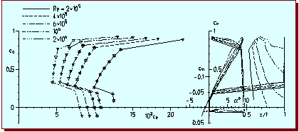
Drag polars of the FX 05-H-126 airfoil.
As a reminiscence to the past, this airfoil is astonishingly well suited for our purpose. Originally this airfoil had been designed and used by the Horten brothers, who built a number of high performance sailplanes during the 1930s and 1940s. Their designs are legend, although some of their published performance data are a little bit too good. There planes were well known for their good handling characteristics, which can be of greater importance that the actual performance figures of a sailplane.
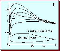
Velocity distribution of the Horten airfoil at 3 different angles of attack.
The velocity distribution of the Horten II airfoil looks quite different from the FX airfoil. The distribution on the upper surface, is much smoother. Due to the blunt leading edge, no suction peaks are visible for the selected angles of attack. The pressure rise (velocity drop) starts near 20% of the chord length, which leads to a less steep gradient. The lift vs. drag characteristics shows smoother polars with no distinctly separated low drag region. The airfoil does not reach the low drag of the FX airfoil.
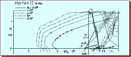
Drag polars of the Horten II airfoil.
The stall characteristics of the Horten II airfoil are smoother than the FX 05-H-126 airfoil, but due to its excessive thickness, it also suffers from boundary layer separation at lower Reynolds numbers. Its moment coefficient is not positive enough for an unswept flying wing. A thinned version of this airfoil with a slightly increased reflex, might be usable for a light, tailless glider.
Instead of trying to modify an existing airfoil a new design has been performed to find a compromise between performance and handling.
During the design of this airfoil, the emphasis has been to design an airfoil, suited for light, man carrying gliders, with moderate wing sweep. While performance was an issue, maximum lift capabilities and good handling qualities were more important. Regarding the usual construction techniques, it was decided to allow transition on the upper surface near 15% of the chord length. The blunt leading edge and the smooth movement of the trailing edge separation is responsible for the comfortable stall characteristics. Flight Reynolds numbers can start at 400'000, where the maximum lift coefficient is approximately 1.4.
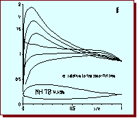
Velocity distribution of the MH 78
at 3 different angles of attack.
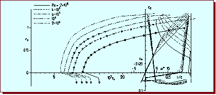
Lift vs. drag polars of the MH 78.
Last modification of this page: 21.05.18
![]()
[Back to Home Page] Suggestions? Corrections? Remarks? e-mail: Martin Hepperle.
Due to the increasing amount of SPAM mail, I have to change this e-Mail address regularly. You will always find the latest version in the footer of all my pages.
It might take some time until you receive an answer
and in some cases you may even receive no answer at all. I apologize for this, but
my spare time is limited. If you have not lost patience, you might want to send
me a copy of your e-mail after a month or so.
This is a privately owned, non-profit page of purely educational purpose.
Any statements may be incorrect and unsuitable for practical usage. I cannot take
any responsibility for actions you perform based on data, assumptions, calculations
etc. taken from this web page.
© 1996-2018 Martin Hepperle
You may use the data given in this document for your personal use. If you use this
document for a publication, you have to cite the source. A publication of a recompilation
of the given material is not allowed, if the resulting product is sold for more
than the production costs.
This document may accidentally refer to trade names and trademarks, which are owned by national or international companies, but which are unknown by me. Their rights are fully recognized and these companies are kindly asked to inform me if they do not wish their names to be used at all or to be used in a different way.
This document is part of a frame set and can be found by navigating from the entry point at the Web site http://www.MH-AeroTools.de/.